Media Configuration
Configuring MediaManager
The configuration of MediaManager is stored in an initialization file. The installation program will create this file with the settings entered during setup. The configuration of MediaManager can be adjusted by editing this initialization file. The service must be restarted for the changes to take effect. If a configuration setting is not found in the initialization file, the default value is used.
Please refer to the appendix of this document for a full description of all configuration parameters in the MediaManager initialization file.
Connections to Surrounding Systems/Components
Configure the following configuration settings appropriately to connect the MediaManager to its surrounding systems or components.
Connection to CTI Server Pair
| Setting | Description |
|---|---|
| HOST_A | Hostname or IP address of CTI server 1 side A |
| PORT_A | Port of CTI server 1 side A. Default is 42027 |
| HOST_B | Hostname or IP address of CTI server 1 side B |
| PORT_B | Port of CTI server 1 side B. Default is 43027 |
| PERIPHERALID | ID of the ICM agent peripheral to which the CTI server is attached (voice PG) |
| APPLICATIONPATHID | Must correspond to ApplicationPathID of “Application_Path” view in ICM AWDB |
Connection to CCE/CCH AWDB
The MediaManager component supports a redundant CCE/CCH AWDB deployment. The initialization file of each MediaManager instance must be adjusted manually to enable the connection to two CCE/CCH AWDBs. Adjust the following configuration parameters in the initialization file of each MediaManager instance:
Configuration for Hot-Standby MediaManager Deployment
The initialization file of each MediaManager instance must be manually adjusted to enable hot-standby deployment. Add the following configuration parameters to the initialization file of each MediaManager instance:
[REDUNDANCY]
THIS_IS_SIDE=
LOCAL_MM_INSTANCE_UDP_PORT=
SECOND_MM_INSTANCE=
SECOND_MM_INSTANCE_UDP_PORT=
Example
MediaManager A Initialization File
[REDUNDANCY]
THIS_IS_SIDE=A
LOCAL_MM_INSTANCE_UDP_PORT=1815
SECOND_MM_INSTANCE=192.168.10.17
SECOND_MM_INSTANCE_UDP_PORT=1815
MediaManager B Initialization File
[REDUNDANCY]
THIS_IS_SIDE=B
LOCAL_MM_INSTANCE_UDP_PORT=1815
SECOND_MM_INSTANCE=192.168.10.16
SECOND_MM_INSTANCE_UDP_PORT=1815
| Setting | Description |
|---|---|
| THIS_IS_SIDE | Specifies the side of the MediaManager instance (A or B) |
| LOCAL_MM_INSTANCE_UDP_PORT | Specifies the port of the local MediaManager instance where heartbeat messages from the other MediaManager instance are received (1024-65535) |
| SECOND_MM_INSTANCE | The IP address of the host where the second MediaManager instance is installed |
| SECOND_MM_INSTANCE_UDP_PORT | The Port on which the second MediaManager instance receives heartbeat messages from the local MediaManager instance (1024-65535) |
MediaManager CCE/CCH Configuration
Step 1: Network VRU Configuration
- For MediaRouting, a Network VRU must be configured. This is only a virtual device in configuration, no real VRU is needed. Explorer Tools – Network VRU Explorer “Add Network VRU” Name: MR_VRU Type: Type 2 Description: VRU for Media Routing PG
Step 2: MediaRouting PG Configuration
Explorer Tools – PG Explorer “Add PG”
Logical controller ID: assigned by the system and required in the CCE/CCH setup
Physical controller ID: assigned by the system and required in the CCE/CCH setup
Name: SAP_CONNECTOR_MEDIA
Client Type: MediaRouting
Configuration parameters:<empty>
Description: MediaManager PG
Physical controller description:<empty>
Primary CTI address:<empty>
Secondary CTI address:<empty>“Save”
If VRU PG and IPCC PG are already found on the same hardware, the IPCC_PG can be defined as “PG Generic” and the VRU can be assigned to it. The new MR PG must then be created.
Tab Peripheral:
Name: MediaManagerRouting
Peripheral name: MediaManagerRouting
Client type: MediaRouting
Location:<empty>
Abandoned call wait time: 5
Configuration Parameters:<empty>
Call control variable map:<empty>
Default desk settings: NONE
Peripheral service level type: Calculated by Call Center
Enable post routing:<selected>Tab Advanced:
Available hold-off delay: 5000
Answered short calls threshold: 0
Network VRU: SAP_CONNECTOR_MEDIA
Agent Auto Configuration:<not selected>Tab Routing Client:
ID: assigned by the system
Name: MediaManagerRouting
Timeout threshold: 2000
Late threshold: 1000
Timeout limit: 10
Default media routing domain: NONE
Default call type: NONE
Configuration parameters:<empty>
Use DN/Label map: Do not use DN/Label map
Client type: MediaRouting
Description:<empty>
Network routing client:<empty>
Network transfer preferred:<not selected>
Congestion Treatment Mode: Default
Default Label:<empty>Tab Default Route: All fields should be left empty. After the settings are saved, the following configuration is displayed:
Media routing domain: Cisco_Voice
Route: NONETab Peripheral Monitor: All fields should be left empty.
“Save”
Please make a note of the automatically assigned Peripheral ID (Tab Peripheral) for later use.
Step 3: MediaRouting PG Setup
Before installing the MediaRouting PG, it is necessary to enable the new PG on the CCE/CCH Router.
PG Setup - Node Manager Properties: Production Mode:
<selected>
Auto Start:<not selected>(only for installation)
Duplexed Peripheral Gateway<selected>PG Node Properties:
No more than 2 PGs can be installed per server. One of them will be selected as the MediaRouting PIM.Client Type Selection:
MediaRouting - “Add” (If it does not yet exist in “Selected Types”)
“Next”
The selected PG must be stopped at this time!
- Add PIM:
Client Type: MediaRouting
Available PIMs: select the next available from the list
“OK”
Enabled:<selected>
Peripheral Name: MediaRouting
ID:<insert here the Peripheral ID here that was generated while creating the peripheral>
Application HostName (1): Server name of the MediaRouting server
Application Port (1): MediaManager MRI listening port. Default is 7021
Application Port (2): Same settings as in (1)
“OK” Enter the Logical Controller ID from the corresponding Logical Control tab in PG Explorer.
“Next” - “Next” - “Next” - “Next” - “Finish” - “Exit Setup”
In Unified CCE Service Control:
The PG can now be restarted.
Step 4: Application Instance Configuration
- In CCE/CCH media routing, each connection to a CTI Server needs its own Application Instance. One Application Instance is needed for MediaManager media routing.
List Tools – Application Instance List
“Add”**
Name: MediaRouting
Application key: MediaManager
Application type:<Other>
Permission level: Read only
Description: MediaManager application
Step 5: Media Classes Configuration
A Media Class is required for each supported media routing medium. See sample Media Classes for email and chat below.
List Tools – Media Class List“Add” for email
Name: MR_Mail
Description: Email routing integration
Life: 300 seconds
Start timeout: 30 seconds
Max duration: 28800 seconds“Add” for chat
Name: MR_Chat
Description: Chat routing integration
Life: 300 seconds
Start timeout: 30 seconds
Max duration: 28800
Step 6: Media Routing Domains Configuration
A Media Routing Domain is required for each supported media routing medium. Below is a sample Media Routing Domain for email and chat.
List Tools – Media Routing Domain List“Add” for e-mail
Name: MR_Mail
Media routing domain ID: is assigned by the system
Media class: MR_Mail
Task Life: 300 (already filled with default from media class)
Task Start timeout: 30 (already filled with default from media class)
Task Max duration: 28800 (already filled with default from media class)
Calls in Queue Max:<empty>
Calls in Queue Max per call type:<empty>
Calls in Queue Max time in queue:<empty>
Service level threshold: 30 (default)
Service level type: Ignore Abandoned Calls
Interruptible:<not selected>
Description:<empty>“Add” for chat
Name: MR_Chat
Media routing domain ID: assigned by the system Media class:
MR_Chat Task Life: 300
Task Start timeout: 30
Task Max duration: 28800
Calls in Queue Max:<empty>
Calls in Queue Max per call type:<empty>
Calls in Queue Max time in queue:<empty>
Service level threshold: 30 (default)
Service level type: Ignore Abandoned Calls Interruptible: not selected
Description:<empty>
Please record the configured Media Routing Domain IDs. These IDs will be required for later steps in installation.
Step 7: Application Path Configuration
- Each application connecting to the CTI server must have its own application path. All media routing domains used by this application must be assigned as members to this application path. See examples below of one Application Path Member for email routing:
List Tools – Application Path List - “Add” Application Path
Application Instance: MediaRouting
Peripheral gateway: Voice PG (!) NOT the MediaRouting PG !
Name: MediaRouting
Description: MediaRouting application path - “Add” Application Path Members for email
Peripheral: Agent PG (CallManager)
Media routing domain: MR_Mail - “Add” Application Path Members for chat Peripheral:
Agent PG (CallManager)
Media routing domain: MR_Chat
After configuring the Application Path, open the Database View “Application_Path” and record the ApplicationPathID the system has assigned to the inserted Application Path. You will need this ApplicationPathID later during the installation of the software. (The ApplicationPathID is not visible in the CCE/CCH configuration GUI, only in the database view.)
Step 8: Call Type Configuration
A Call Type is required for each supported media routing medium. See a sample Call Type for emails below.
List Tools – Call Type List“Add” for email
Name: MR_Mail
Customer:<None>
Description: CT for Media Routing email“Add” for chat
Name: MR_Chat
Customer:<None>
Description: CT for Media Routing Chat
Step 9: Dialed Number / Script Selector Configuration
One or more Script Selectors are required to route media tasks via the CCE/CCH script.
The name of the Script Selector is used for route requests on the MediaManager MCIL interface.
Below are sample Script Selectors for email and chat.
List Tools – Dialed Number / Script Selector List“Add” Dialed Number / Script Selector for email
Routing client: MediaManagerRouting
Media routing domain: MR_Mail
Dialed number string / Script selector: Valid email address (must be in lowercase!)
Name: MR_MAIL
Customer:<none>
Default label:<none>
Description: DN for email routing
Permit application routing:<not selected>
Reserved by IVR:<not selected>
Dialed Number Mapping: Assign the corresponding CallType for each Script Selector here“Add” Dialed Number / Script Selector for chat
Routing client: MediaManagerRouting
Media routing domain: MR_Chat
Dialed number string / Script selector: Valid chat address (must be in lowercase! Use complete JIDs \<node>\@\<domain>)
Name: MR_CHAT
Customer:<None>
Default label:<None>
Description: DN for chat routing
Permit application routing:<Not selected>
Reserved by IVR:<Not selected>
Dialed Number Mapping: Assign the corresponding CallType for each Script Selector here
Step 10: Label List Configuration
In case of an error, the CCE/CCH script returns predefined labels. It is recommended to configure the following labels and use them in the CCE/CCH scripts:
List Tools – Label ListRouting client: MediaManagerRouting
Label: Timeout
Label type: Normal
Target type:<None>
Network target:<None>
Customer:<None>
Description: No agent found, timeout with target re-query of third- party systemRouting client: MediaManagerRouting
Label: Overflow
Label type: Normal
Target type:<None>
Network target:<None>
Customer:<None>
Description: The task could not be queued because the maximal number of queued tasks has been reachedRouting client: MediaManagerRouting
Label: Error
Label type: Normal
Target type:<None>
Network target:<None>
Customer:<None>
Description: Non-recoverable error, do not attempt to reroute again
Step 11: Skill Group Configuration
- Explorer Tools – Skill Group Explorer
Peripheral: Agent PG (CUCM) - “Add Skill group” for email
Tab skill group:
Media routing domain: MR_Mail
Peripheral number: skill group number
Peripheral name: skill group name
Name: skill group – Name (e.g. EM [ skill group name])
Available holdoff delay (sec):<default>
ICM picks the agent:<selected>
Other tabs:
Default or defined - “Add Skill group” for chat
Tab skill group:
Media routing domain: MRChat
Peripheral number: skill group number
Peripheral name: skill group name
Name: skill group – Name (e.g. EM[ skill group name])
Available holdoff delay (sec):<default>
ICM picks the agent:<selected>
Other tabs: Default or defined
Step 12: Service Configuration
One or more Services can be configured for each media routing domain.
Explorer Tools – Service Explorer
Peripheral: Agent PG (CUCM)“Add Service” for email
Tab Service: Media routing domain: MR_Mail
Peripheral number: Service number
Peripheral name: Peripheral service name
Name: Service – Name (e.g. EM [peripheral service name])
Tab Service Members:
Add email skill groups, select Primary for all
One route is required for each service.
“Add Route” for email
Route: Name: MR_Mail“Add Service” for chat
Tab Service:
Media routing domain: MRChat
Peripheral number: Service number
Peripheral name: Peripheral service name
Name: Service – Name (e.g. EM[peripheral service name])
Tab Service Members:
Add chat skill groups, select Primary for all
One route is required for each service.
“Add Route” for chat
Route: Name: MR_Chat
Step 13: Script
- Once all configuration tasks are done, create the CCE/CCH Routing Script.
MediaRouting tasks are queued for several days. The "Wait Time“ must cover
this period. The Timeout-Label works as a system failure and informs the
third-party system that the route request must be resent.
Sample CCE/CCH Routing Script If the Script Selector is known, the longest available agent is selected with the "Select - LAA" node. If no agents are currently available, the task will be queued with the "Queue to Skill Group" node. Because tasks can be routed to CCE/CCH even if only the MR PG (media routing peripheral) is operational and the CUCM PG (agent peripheral) is down, there is a check to verify the operability of the CUCM PG. This check is required because the "Queue to Skill Group" would not work under the aforementioned circumstances. If the CUCM PG is identified as not operational, the label “Timeout” is returned.
The if-condition is:
(Peripheral.\<AgentPeripheralName>.Online==1)&&(Peripheral.\<AgentPeripheralName>.Mode==1)Peripheral Mode = Current mode of the peripheral as reported by the PG: 0 = off-line; 1 = on-line.
Peripheral Online = Current on-line state of the peripheral as determined by the Central Controller: 0 = off-line; 1 = on-lineIf the task cannot be queued (due to MaxCalls or MaxCallsPerCallType), the label "Overflow" is returned.
After the task is queued, a “Wait” Node is called with a time lower than the system limit (MaxTimeInQueue). If this wait time expires, queuing is cancelled and a label “Timeout” is returned.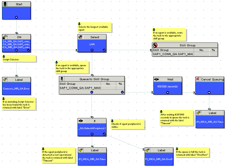
A common problem of the simple script above is that tasks, rerouted because of a timeout or other reasons, are added again to the end of the queue just like an initial routed task.
Also, there is no additional information available later to differentiate initial routed tasks from rerouted tasks.
Step 14: MaxQTime Configuration
- The maximum duration of queued tasks has to be increased in the registry on both CCE/CCH Routers to 432,000 (5 days).
HKLM\SOFTWARE\Cisco...\<instance>\RouterA\Router\CurrentVersion\Configuration\Queuing\MaxTimeInQueue
- The settings on the PGs are not relevant in this case and can be left as they are. The "Wait“ that occurs in the script before the timeout, has to be shorter and should be set to a maximum value of 430,000.
After creating the script, the CallType for this script must be scheduled. - It is important that the data timeout configuration settings of the CRMConnectorSAP and the DataStore (if used) are set to the correct value.
Please refer to the appendix of this document for more detailed information about the meanings and default values of these settings.
CRMConnectorSAP
DataStorePhoneExpirationTimeout
DataStoreMailExpirationTimeout
DataStoreChatExpirationTimeout
RouteRonaTryCount
RouteTryCount
RouteTimeout
RouteWaitToRerouteTimeout
RouteRoutingSessionLimit
TransactionDefaultTimeout
TransactionDoMakeCallTimeout
TransactionWorkTimeout
DataStore
DeleteTimeout
ExpirationTimeout
Step 15: Activate the Routing Script
- To activate the CCE/CCH media routing script you have to schedule it with the Call Type Manager of the Script Editor the same way you schedule a script for voice calls.
Configuring ChatConnector
The configuration of ChatConnector is stored in an initialization file. The installation program creates this file with the settings entered during setup. The configuration of ChatConnector can be adjusted by editing this initialization file or by using a remote console connection. In both cases the service must be restarted for the changes to take effect. If a configuration setting is not found in the initialization file, the default value is used.
Please refer to the ChatConnector Inizialization File for a full description of all configuration parameters in the ChatConnector’s initialization file and check the Chat Feature document for a description of the basic concept and most important configuration steps for deploying the b+s Connects for SAP’s chat channel.
Configuring DataStore
The configuration of DataStore is stored in an initialization file. The installation program will create this file with the settings entered during setup. The configuration of DataStore can be adjusted by editing this initialization file. The service must be restarted for the changes to take effect. If a configuration setting is not found in the initialization file, the default value is used.
Please refer to DataStore Inizialization File for a full description of all configuration parameters in the DataStore initialization file.